| |
|
The ultrasonic principle is based on the fact that
solid materials are good conductors of sound waves. Whereby
the waves are not only reflected at the interfaces but also
by internal flaws (material separations, inclusions, discontinuities,
etc).
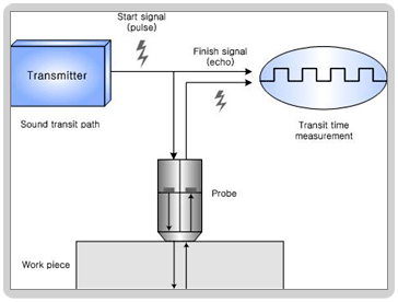
It is said to "Pulse-Echo method".
A pulse-echo ultrasonic thickness gauge determines the thickness
of a part or structure by accurately measuring the time required
for a short ultrasonic pulse generated by a transducer to
travel through the thickness of the material, reflect from
the back or inside surface, and be returned to the transducer.
In most applications this time interval is only
a few microseconds or less.
The measured two-way transit time is divided by two to account
for the down-and-back travel path, and then multiplied by
the velocity of sound in the test material.
The result is expressed in the well-known relationship :
S=CT/2 (ideal case) ---------- Formula 1
Where S = sound transit path
[mm] of the work piece
C : the velocity [km/s] of sound waves in the material
T : the transit time of flight [¥ìs] being measured by Internal
Counter

Figure 1. Block diagram : Pulse Echo
Method
Additionally, in actual practice, a Probe Zero is usually
subtracted from the measured time interval to account for
certain fixed electronic and mechanical delays. In the common
case of measurements involving direct contact transducers,
the Probe Zero compensates for the transit time of the sound
pulse through the transducer's wearplate and the couplant
layer, as well as any electronic switching time or cable delays.
This Probe Zero is set as part of instrument calibration procedures
and is necessary for highest accuracy and linearity.
S=C(T-T0)/2 (real case) ---------- Formula 2
Where T0 : the time of initial pulse [¥ìs], viz. probe
zero
In case user already know the sound velocity of the material
being measured
You can measure the thickness of work piece by inputting known
velocity value directly into Formula 2.
In case user don't know the sound velocity of the material
being measured
You must make use of a test piece of the same material as
the work piece whose dimensions are known in order to measure
accurate thickness. In formula 2, you already knew
values as sound transit path, time of flight, time of initial
pulse. Therefore, you can calculate the sound velocity of
test piece. This data is used to calculate the work piece
you want to measure.
If you don't know both velocity and thickness of work piece,
you can't measure it.
In this case, however, you can select the similar value as
work piece in the sound velocity table for the various materials.

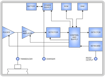
Figure 2. The system architecture
of pulse-echo ultrasonic thickness gauge
Figure 2 represents a generalized block diagram
of a modern microprocessor-controlled ultrasonic gauge. The
pulser, under control of the
microprocessor, provides a unidirectional broadband voltage
impulse to a heavily damped broadband ultrasonic transducer.
The broadband ultrasonic pulse
generated by the transducer is coupled into the test piece,
normally with the aid of a liquid coupling medium. Returning
echoes are received by the transducer and converted back into
electrical pulses, which in turn are fed to the receiver Automatic
Gain Control (AGC) amplifier. The microprocessor-based
control and timing logic circuits both synchronize the pulser
and select the appropriate echo signals to be used for time
interval measurement.
If echoes are not detected during a given measurement period,
the gauge will shut down to save power until a new measurement
cycle is required. If echoes are detected, the timing circuit
will precisely measure an interval appropriate for the selected
measurement mode, and then repeat this process a number of
times to obtain a stable, averaged reading.
The microprocessor then uses this time
interval measurement, along with the sound velocity and Probe
Zero information stored in the Random Access Memory (RAM),
to calculate thickness.
This thickness measurement is then displayed on the
Liquid Crystal Display (LCD) and updated
at a selected rate (viz. Pulse Repetition
Frequency).
Many modern gauges incorporate an internal data logger and
are capable of storing several thousand thickness measurements
along with identification codes and setup information in RAM.
These stored readings may be recalled to the gauge's display
or uploaded to a printer or computer for further analysis.
|
